

When setting up your views for the MEP disciplines, configuring view range in Revit can be confusing at first. Our previous post walked you through how to make MEP elements in the ceiling space visible on floor plan views using view range settings. For this post, we’ll show you how to show MEP elements that are below or cast in the floor (e.g., pipes and conduits).
If you need to understand the basics of configuring the View Range of a floor plan, see part one of this series.
When setting up your views for the MEP disciplines, configuring their view ranges in Revit can be confusing at first.
View Range for MEP Elements Below or Within a Floor
In our previous post, we looked at how to set the top and cut plane of the primary range to show elements above the ceiling. For today, we’ll focus on the elements that are below floor.
Technically, the only view range setting that needs to be adjusted to show elements below floor is the View Depth. In the example below, you can see that I have a sanitary pipe modeled below the floor at
–2’. You will also notice that the pipe is visible when the View Depth is set to -2’, because it now lies within the View Range.
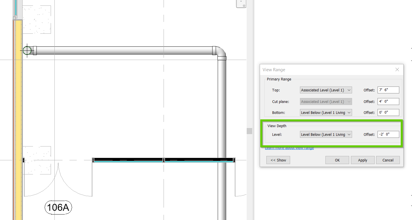
That seems pretty straightforward, so why write a blog about something so simple? Well, you may have noticed that in the View Range window, there is a setting for Bottom within the “Primary Range” section. This can prove to be confusing, even for some of the more experienced Revit users.

Why Do We Need Both “Bottom” and “View Depth”?
Let’s refer back to Autodesk’s image within the View Range window (click the Show button in the lower right corner to display the image within Revit).
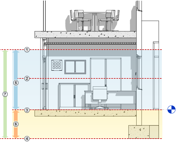
First, let’s review some of these keynotes:
7. The entire View Range
5. The Primary View Range
3. The Bottom of the Primary View Range
4. The View Depth setting
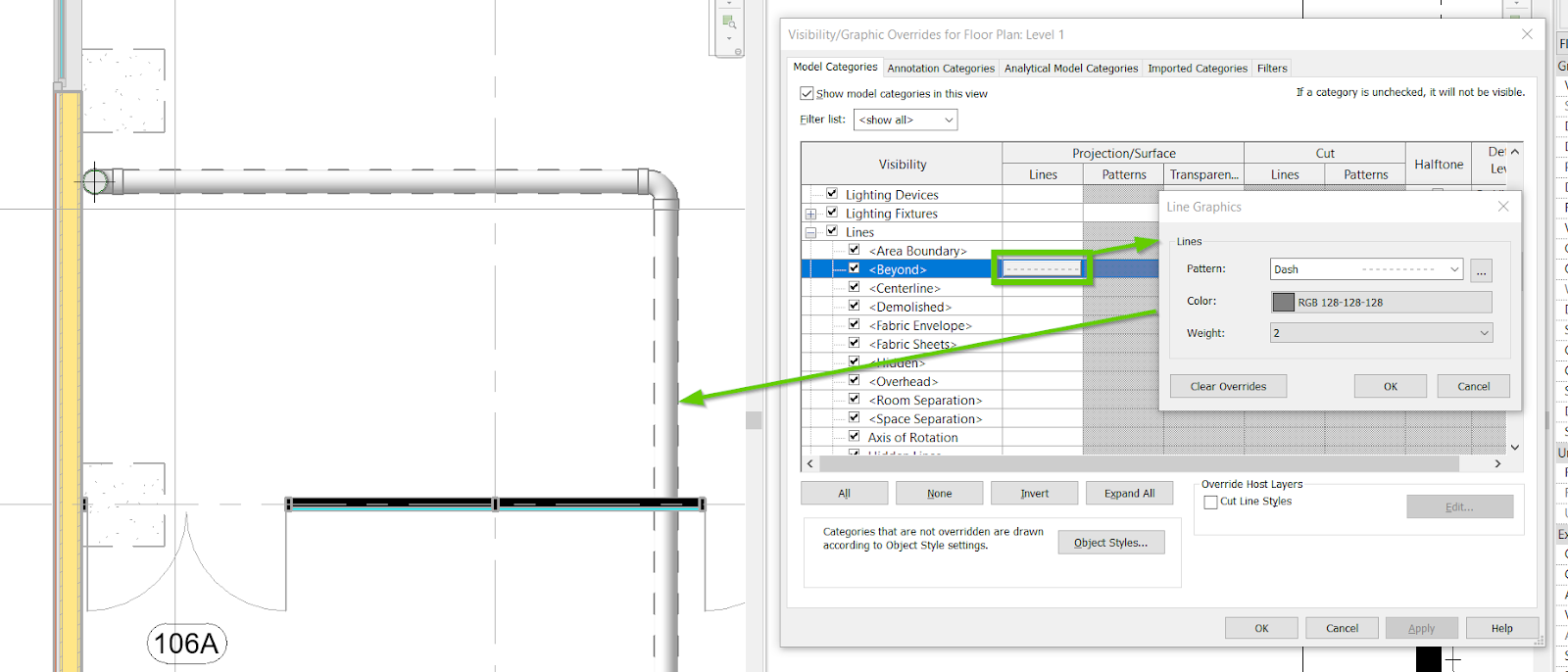
With those numbers in mind, let’s think about a floor plan and the concept of showing something that is below the floor. Typically, elements that live below the floor plan (i.e., underfloor, underground, within a raised floor) will be drawn as a dashed line. This helps anyone reviewing a floor plan understand that the pipe, duct, or conduit is not overhead as most floor plans illustrate as solid lines. This has been standard practice since we were drafting plans with pencil and paper and Revit handles it rather gracefully using the view depth of a View Range.
In simple terms, any element that is below the Bottom of the Primary View Range and above the View Depth (i.e., the yellow area in the illustration above), is considered to be “beyond” the primary view range. So, you can still see the element in a plan view, but it not within the Primary View Range.
This is important, because Revit has a built-in sub-category of Line styles called “”. This means you can make any element a dashed line when it is within the View Depth of the floor plan view. Thus, any underfloor duct, pipe, conduit, or footings can now automatically be displayed as dashed lines when it lives below the Bottom of the Primary View Range.
Conclusion
I hope that these two blog posts will help some of our MEP readers out there understand some of the lesser-known basics of configuring View Range.
Do you have any additional tips and tricks to share regarding view range? Please share them in the comments below.