
When setting up your views for the MEP disciplines, configuring their view ranges in Revit can have somewhat of a steep learning curve. In this two-part blog series, I’ll cover some techniques one how to properly show/hide MEP elements that are typically above the ceiling or below the Level of a floor plan.
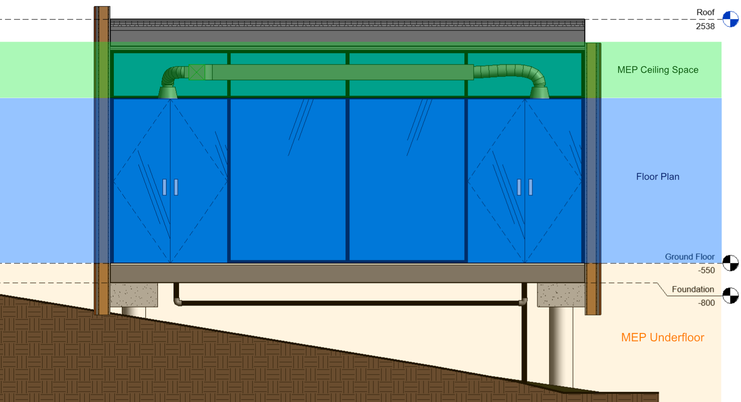
In the illustration above, the green area is what you would typically see on a floor plan view. You would expect to see elements such as door swings, windows, furniture, or even receptacles on a floor plan that includes this 3-dimensional space in the view range. When working with MEP disciplines, however, things get quite a bit more complicated, as there are typically several MEP elements that are designed in the ceiling space or even below the floor.
Setting the View Range of a View
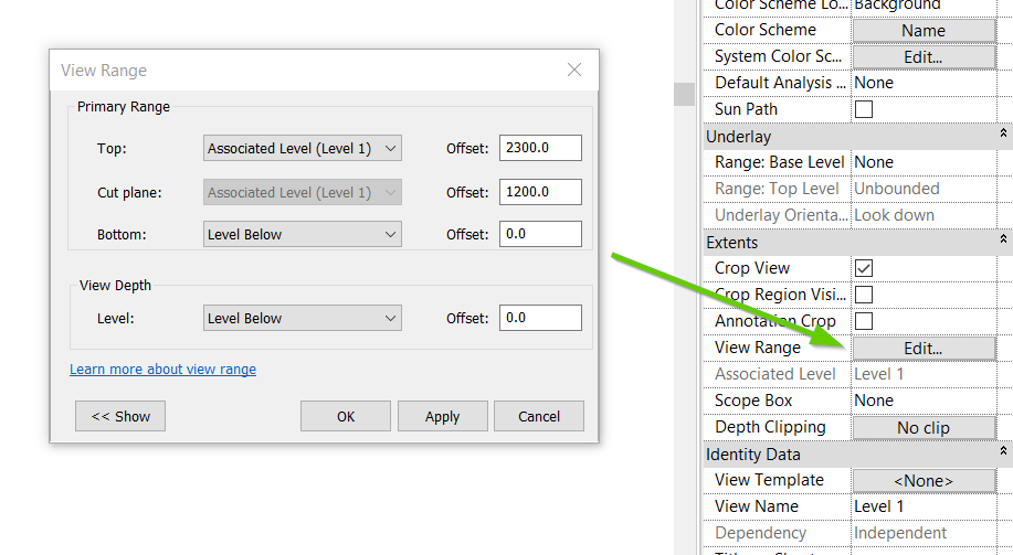
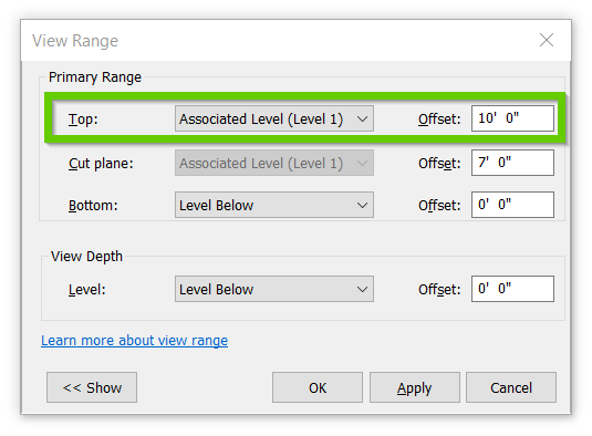
To set the view range of a view, open your Properties pane and click the Edit button next to View Range (under the Extents group). This opens the View Range dialog, where you can adjust values for Top, Cut Plan, Bottom, and View Depth… But what does all of this mean?
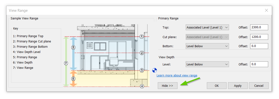
In recent versions of Revit, Autodesk has provided a handy little button on the view range dialog which displays a quick reference for what these terms mean. Although these terms are clearly illustrated in the View Range window, adjusting these settings for MEP elements can still be a bit confusing.
 View Range for MEP Elements Above the Ceiling
For part one of this two-part blog series, we’ll walk through setting up a view range on a floor plan view and cover the view range terms as they apply to MEP elements within the ceiling space. The terms Top, Cut Plane, and Bottom all seem to make sense, so let’s adjust the view range in my floor plan view to include the duct within the ceiling space of my model.
Primary Range: Top
There are two main schools of thought when setting the Primary Range of the view range to include the elements that are in the ceiling space.
1. Set the Top to Level Above, with a negative offset. This ensures that if and when the floor-to-floor heights change, your view will still include the ceiling elements. When using this method to set the top of your view range, be sure to compensate for the thickness of the floor in your negative offset so you don’t include any pipes or conduit that is installed in the floor or cast in the slab. For example, if the level above is at 13’-0” with a 8” thick slab, set your offset to -0’-8”.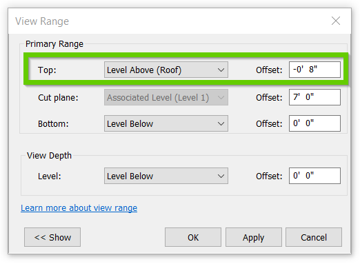
Primary Range: Cut Plane
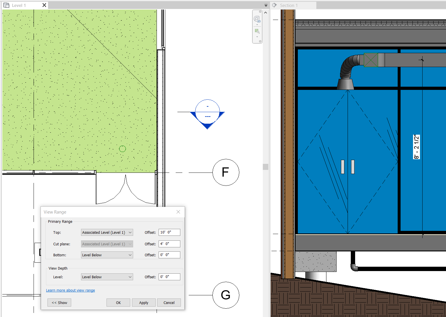
In the left window (Level 1) in the image above, you can see my floor plan view with the Top of the Primary Range set to 10’-0” above the Associated Level (Level 1), but no ductwork is visible even though you can clearly see that the duct that I’ve modeled in the right window (Section 1) is well within the Primary Range. What’s going on?
The Cut Plane offset in your View Range needs to be taken into account. The rule of thumb is that you’ll need that plane to be set either to above your duct, or cutting though your duct.
Now that we’ve set the Cut Plane to 8’-0” above the Associated Level, we still aren’t seeing the ductwork and actually after adjusting our view range, the floor plan looks even further than goal than it did earlier.
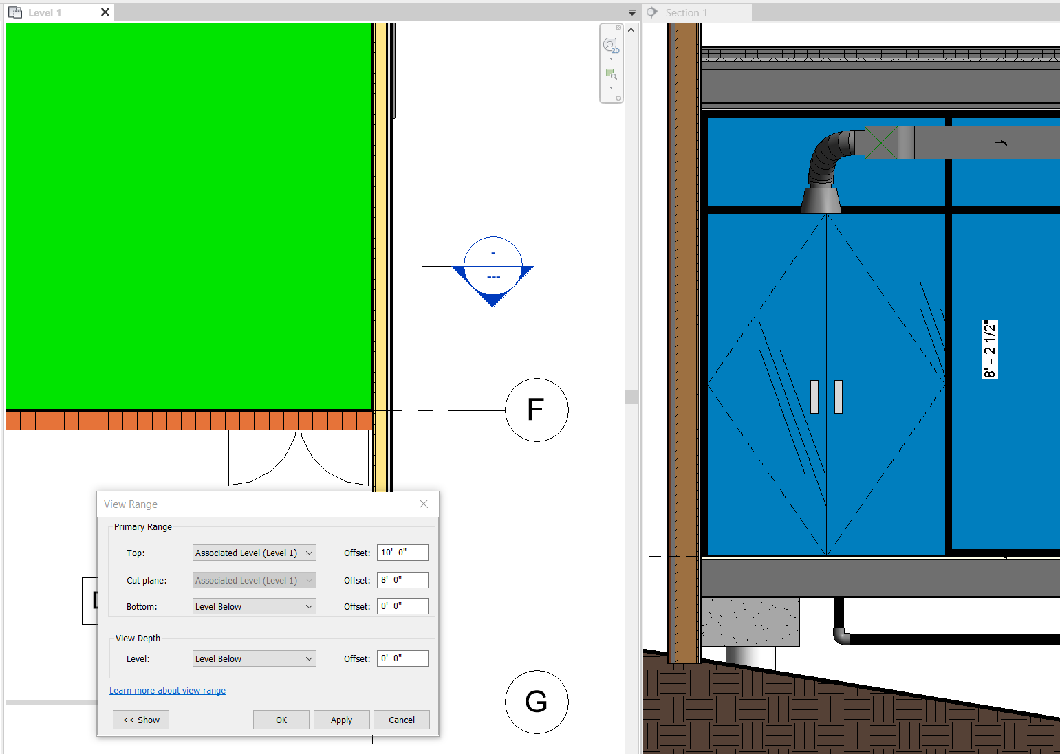
Before you hit CTRL+Z on your keyboard, let’s have a look at what’s happening here. Select the opaque object and look at your Properties pane.
As you can see, it is in fact the ceiling that is blocking my ductwork from being visible in the view. The proper way to fix this issue is relatively simple: turn off visibility of the Ceilings category in Visibility/Graphic Overrides.
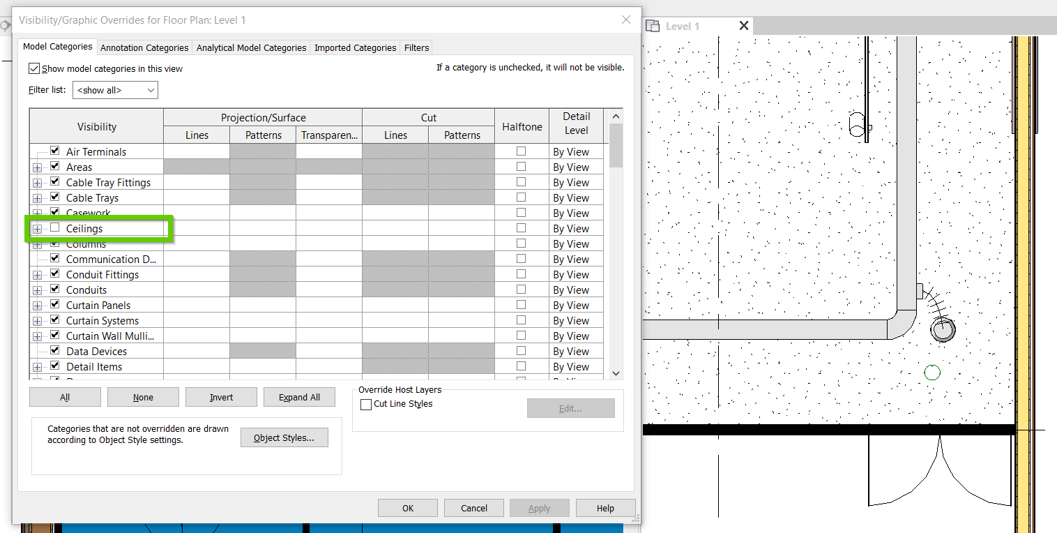
As you can see now, our view range is properly set and I can see the ductwork within the ceiling space of this floor plan.
Primary Range: Bottom and View Depth
In the context of setting a view range to include ceiling spaces, the Bottom and View Depth settings are less relevant, so we can keep them at 0’-0” for now.
Conclusion
Controlling visibility of elements in a view is one of the biggest hurdles when learning Revit and setting a correct view range is just one possibility of why you aren’t seeing your elements.
Watch this space for part two of two in this series, as we walk through how to deal with piping that is below the floor and how to deal with those pesky rise/drop symbols of pipe fittings.